
Introduction: The Confusing Negative Reading on Energy Meters
The global transition toward renewable energy has led to a rapid increase in the installation of distributed solar photovoltaic (PV) systems on commercial, industrial, and residential facilities. To monitor energy production, consumption, and export back to the utility grid, B2B engineers and solar installers rely heavily on digital DIN-rail energy meters.
However, during the commissioning phase of a solar-grid setup, installers often report a baffling issue: the digital DIN-rail energy meter displays a negative power reading (for example, -5.4 kW) or shows a reverse energy flow indicator (often marked as 'REV' or 'EXP'). To those unfamiliar with the electrical dynamics of grid-tied solar systems, a negative power reading can seem like an error or a faulty meter. In reality, this reading is a highly logical response to the direction of electrical power flow. This comprehensive guide covers the technical reasons behind negative energy readings, how current transformers (CTs) determine power direction, and how to configure and wire your metering system correctly.
The Physics of Power Flow and Sign Conventions in Grid-Tied Systems
To understand why an energy meter shows a negative reading, we must analyze the two-way relationship between a grid-tied facility and the utility power grid.
In a traditional consumer-only facility (without solar panels), power flow is strictly unidirectional. Electricity flows from the utility grid, through the main service panel, and into the facility's electrical loads. By standard industry convention, this imported power is defined as positive power (+).
When you integrate a solar PV system with a grid-tied inverter, the facility becomes a prosumer (both a producer and consumer of electricity). This setup creates two distinct power flow scenarios:
If the solar system is producing 3 kW but the facility's machinery and lights are drawing 10 kW, the solar power is fully consumed on-site. The remaining 7 kW is imported from the utility grid. The energy meter measures this import as positive power (+7 kW).
During peak daylight hours, the solar system may generate 15 kW of power, while the facility is only drawing 5 kW. Because electricity follows the path of least resistance, the excess 10 kW of solar energy cannot be stored (unless batteries are present). Instead, it automatically flows backward out of the facility, through the energy meter, and exports into the utility grid. By standard industry convention, exported power is defined as negative power (-10 kW).
Therefore, a negative power reading is often not an error, but a normal indication that your solar PV system is actively exporting excess clean energy back to the grid.
Common Technical Issues Causing Erroneous Negative Readings
While a negative reading is normal during peak solar export, if you observe a negative power reading when your solar system is turned off, or if you are measuring a circuit that should only consume power, you are facing an installation error. The most common technical causes include:
1. Reversed Current Transformer (CT) Orientation
Most industrial DIN-rail energy meters utilize external Current Transformers (CTs) to measure AC current without physically splicing high-current cables. A CT is a donut-shaped magnetic sensor placed around the active power line.
CTs are highly directional. They have a designated polarity and feature markings such as 'P1' and 'P2' (or 'Source' and 'Load') on their casing, and 'S1' and 'S2' on their output terminals. If a CT is physically clamped onto the wire backward (with P1 facing the load instead of the source), the current signal is phase-shifted by 180 degrees. This phase shift causes the meter's microprocessor to calculate active power as negative, even though power is flowing in the positive direction.
2. Misaligned Voltage and Current Phase Wiring (Multi-Phase Meters)
In three-phase electrical systems, a multi-phase DIN-rail energy meter must measure both the voltage and the current for each individual phase (Phase A, Phase B, and Phase C) to calculate total active power.
If the voltage connection for Phase A (V1) is wired to the meter, but the current transformer for Phase B (CT2) is incorrectly associated with Phase A's measurement channel, the resulting phase-angle calculation will be completely incorrect. This cross-phasing error often results in random, high-value negative power readings on one or more phases, severely distorting the total power calculation.
3. Spliced or Reversed CT Secondary Leads
The small wires connecting the CT output to the meter (typically labeled S1 and S2, or black and white leads) must be wired to the correct terminals on the energy meter. Splicing these wires or reversing their connection at the meter terminals will reverse the current phase angle, producing an erroneous negative power display.
Step-by-Step Installation Troubleshooting Checklist
If your DIN-rail energy meter is showing a negative reading, use this structured checklist to diagnose the cause:
Step 1: Check Solar PV System Active Status
Turn off the main solar inverter AC circuit breaker so that the solar system is completely isolated and cannot generate power.
Step 2: Verify CT Physical Orientation
Locate the current transformers clamped around the main incoming lines.
Step 3: Match Voltage and Current Phases
For three-phase systems, physically trace the wires from the main breaker to the meter terminals.
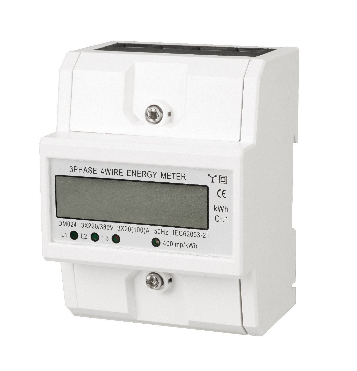
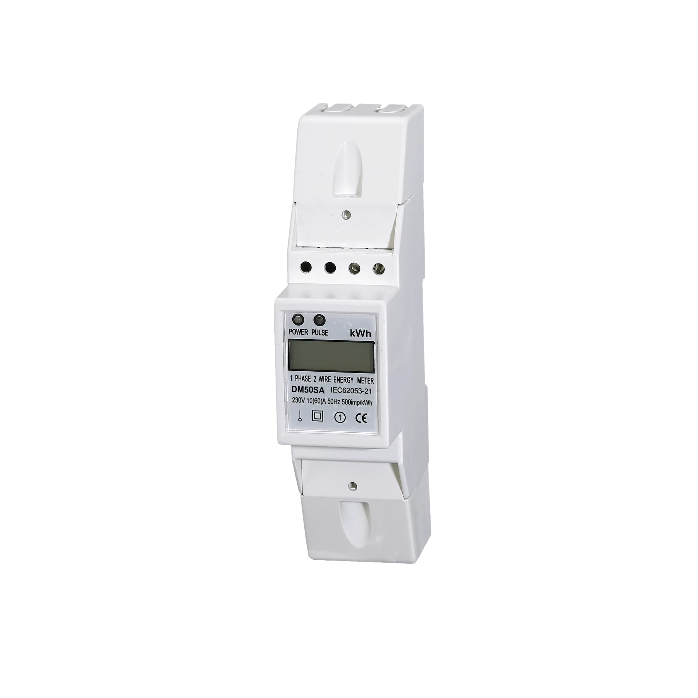
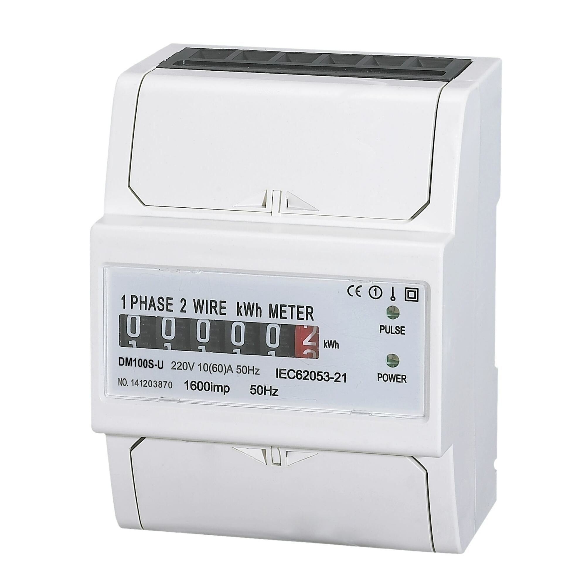
Sourcing Bi-Directional Meters: The DAQCN Advantage
In solar-grid installations, it is critical to use a true Bi-Directional (or four-quadrant) smart energy meter rather than a standard unidirectional meter. Standard meters cannot distinguish the direction of power flow and may accumulate exported solar power as imported energy, leading to double-billing by the utility company.
At DAQCN, we manufacture advanced DIN-rail digital energy meters designed specifically for solar-grid and smart energy management applications:
Conclusion: Mastering Solar Metering Systems
A negative power reading on a DIN-rail energy meter in a solar-grid setup is a normal, healthy indicator of excess power export—provided the solar inverter is running. If the solar system is off and the reading remains negative, the culprit is almost certainly a reversed CT clamp or a phase-matching wiring error. By systematically validating physical CT directions and matching voltage-current phases, installers can ensure precise, high-fidelity energy data. Choosing bi-directional, high-precision metering solutions from DAQCN ensures your solar projects are commissioned quickly, accurately, and professionally.
Discover DAQUAN’s CE/TUV-certified relays, timers, energy meters & WiFi smart switches for industrial automation. ISO9001 factory in Wenzhou, 30 km to airport, global OEM/ODM.
No. 172, Xinguang Avenue, Xinguang Industrial Zone, Liushi Town
Copyright © 2026 WENZHOU DAQUAN ELECTRIC CO.,LTD All rights reserved. Privacy Policy
 Hot News