
Q: How do I set the overvoltage and undervoltage thresholds on a DIN-rail voltage protector for a 220V single-phase supply?
A:
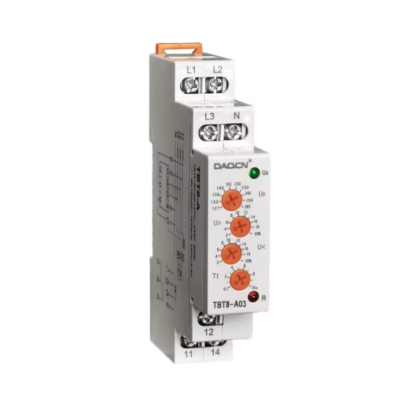
A DIN-rail voltage protector disconnects the load whenever the incoming voltage leaves a band you program. On adjustable models such as the DAQUAN JGQ and JGKL series, the real question is not which number looks standard, but what this load can safely tolerate. Before touching the keys, make five decisions: undervoltage trip point, overvoltage trip point, recovery level, action delay, and reclose delay. The ranges below reflect common practice for 220V single-phase systems. Confirm every final value against the nameplate, the datasheet, and the instruction manual of your exact model.
1. What the protector does before you set anything
•The unit measures L-N voltage continuously and opens its internal contacts when voltage stays below the undervoltage set point, or above the overvoltage set point, for longer than the programmed action delay.
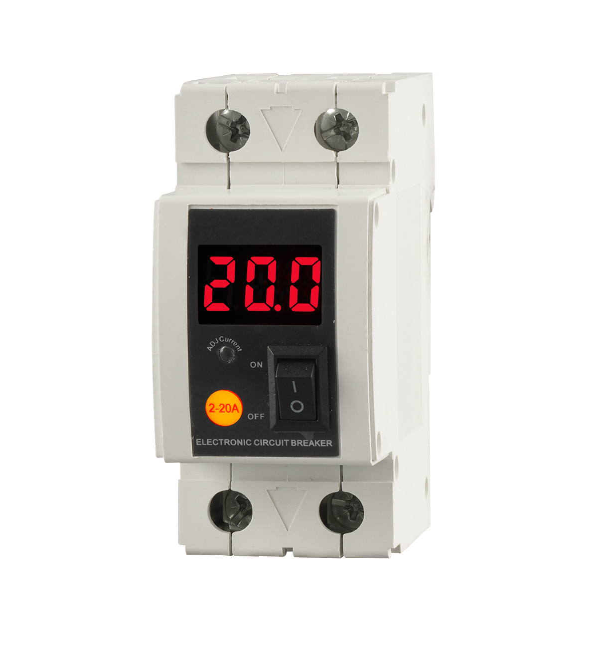
•JGQ and JGKL series units display live voltage on an LED screen, so compare the readout with a calibrated meter before changing anything.
•Both series are self-recovering: once the supply returns inside the band for the programmed reclose delay, the unit re-energizes the load by itself.
•Every entered value must fall inside the adjustable window printed on the nameplate. Values outside the window are rejected or ignored.
2. Set the undervoltage and overvoltage trip points from the load profile
•Undervoltage: on a 220V system, engineering practice usually places the trip point between roughly 170V and 190V. Start near 180V for a general mixed load.
•Move toward 185-190V when the load is brownout-sensitive, such as VFD drives, PLC supplies, refrigeration controllers, or medical and data equipment, which misbehave before a hard undervoltage arrives.
•Move toward 170V only for tolerant loads, long feeders, or sites with deep but brief dips that cannot be eliminated. Keep the value inside the nameplate window.
•Overvoltage: common practice is about 250-270V, starting near 255-260V for general loads. Most 230V-rated equipment accepts about 253V continuously, so 250-255V protects with few nuisance trips on a regulated supply.
•Set 260-270V only when the site runs near the top of the tolerance band and the connected equipment is rated for it; sensitive electronics justify the lower end of the window.
3. Keep a recovery gap so the unit does not hunt
•The reclose condition must sit above the undervoltage trip with a margin, or a supply hovering near the trip level cycles the load on and off.
•In practice, require a return to a clearly healthy level, typically about 200V or above on a 220V system, before the reclose delay starts. The exact recovery value and adjustable hysteresis are model specific; check the nameplate and datasheet.
4. Set action and reclose delays with compressors in mind
•The action delay filters transients: a dip of a few hundred milliseconds is usually a motor start, not a supply failure, and roughly 1-3 seconds of delay catches sustained undervoltage while ignoring such dips. Available values depend on the model.
•The reclose delay protects mechanical loads. Compressors and refrigeration equipment must not restart immediately after a trip, because head pressure is high and short-cycling damages the compressor.
•If the model allows a reclose delay in minutes, set at least 2-3 minutes for compressor duty and more for large refrigeration racks. If the delay is fixed, verify from the datasheet that it suits your restart behavior.
•Fans, pumps, and resistive loads accept shorter delays; the goal is to prevent rapid on-off cycling.
5. General key-setting logic on JGQ and JGKL units
•The JGKL1-63 operator panel uses SET, UP, and DOWN keys and a three-color LED that scrolls voltage, current, frequency, and energy values. JGQ series follows the same family logic, but layouts differ between models.
•The general sequence: press SET to enter setting mode, press SET again to step through parameters, use UP or DOWN to change the displayed value, and save by confirming or by letting the unit exit the menu automatically.
•Set the parameters in order: undervoltage point, overvoltage point, action delay, then reclose delay if adjustable. A long press usually enters or leaves the menu, and holding UP or DOWN scrolls faster; follow the manual shipped with the unit.
•After programming, record every value in the cabinet documentation.
6. Adapt the settings to the grid quality of the site
•Weak rural grids and long feeders see dips and slow swings: set the undervoltage trip toward the lower end of the window and use a longer action delay so routine dips do not disconnect the load.
•Generator-backed supplies: small generators regulate voltage poorly under load steps. Check the generator AVR first; if output genuinely wanders, widen the corridor and lengthen the delays.
•Industrial parks and urban grids are stable, so standard values apply. If a large neighbor load on the same transformer drags voltage down at certain hours, log the supply before narrowing thresholds.
•When a site mixes sensitive electronics and motors, set the corridor for the most sensitive equipment and the delays for the heaviest mechanical load.
7. Verify against the nameplate before closing the cabinet
•Compare your values with the adjustable range on the nameplate and the factory default table in the datasheet. If a value looks wrong on the display, step back through the menu and confirm which parameter you are editing.
•Watch the display through a normal operating day: the unit should stay closed during brief dips and trip only when the supply leaves the band for longer than the delay. When in doubt, restore factory defaults and re-enter the values slowly.
Discover DAQUAN’s CE/TUV-certified relays, timers, energy meters & WiFi smart switches for industrial automation. ISO9001 factory in Wenzhou, 30 km to airport, global OEM/ODM.
No. 172, Xinguang Avenue, Xinguang Industrial Zone, Liushi Town
Copyright © 2026 WENZHOU DAQUAN ELECTRIC CO.,LTD All rights reserved. Privacy Policy
 EN
EN
 Hot News