
Introduction: The Challenge of SSR Failure to Turn Off
In industrial automation and control panels, the Solid State Relay (SSR) is a cornerstone component. Unlike traditional electromechanical relays, SSRs offer rapid switching speed, silent operation, and an exceptionally long operational lifespan due to the absence of moving parts. However, industrial engineers, electrical contractors, and maintenance teams frequently encounter a frustrating symptom: the Solid State Relay remains in an ON state, continuing to power the load, even when the control input signal is completely disconnected.
This phenomenon can lead to severe operational issues, machine downtime, or safety hazards, such as heating elements running continuously or motor loads refusing to shut down. For B2B procurement managers and plant engineers, understanding why an SSR fails to turn off and knowing how to resolve residual voltage and leakage current issues is critical. This guide provides a detailed technical analysis and step-by-step solutions to ensure your control circuits operate safely and reliably.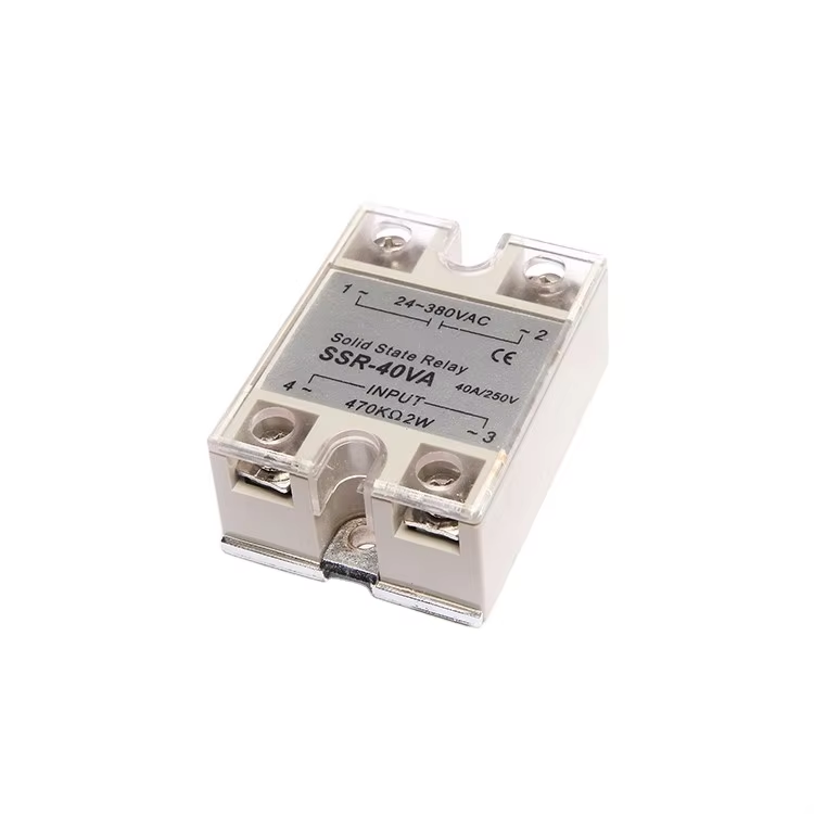
Understanding the Semiconductor Physics Behind SSR Leakage Current
To troubleshoot why an SSR stays ON, we must first understand how a solid state switching device differs from a mechanical contact. A mechanical relay physically separates physical contacts, creating an air gap with near-infinite electrical resistance. When a mechanical relay is open, leakage current is zero.
An SSR, however, relies on semiconductor materials (typically Triacs, SCRs, or MOSFETs) to block or conduct current. Semiconductors do not create an physical air gap. Even in their off-state, semiconductor devices exhibit a small amount of leakage current, usually ranging from 1 to 10 milliamperes (mA). Under normal circumstances with high-wattage loads, this small leakage current passes unnoticed because the load has a low impedance. However, if the load has a high impedance or is extremely sensitive, this tiny off-state leakage current is sufficient to keep the load energized or produce a high residual voltage across the load terminals.
Common Causes for SSRs Staying ON
There are several technical reasons why an SSR might stay ON or fail to drop out when the input voltage is removed. Let us explore the most common causes:
1. High Off-State Leakage Current
As mentioned, all SSRs have a specified off-state leakage current. In low-power circuits, such as those controlling small solonoids, high-impedance indicators, or small electronic controllers, this leakage current can keep the load turned on. The load simply does not draw enough current to allow the SSR semiconductor junction to return to its non-conducting blocking state.
2. Transient Overvoltages and DV/DT Spikes
AC Solid State Relays typically use Thyristors or Triacs. These components are sensitive to the rate of change of voltage over time, mathematically expressed as dV/dt. In industrial environments with inductive loads (such as motors, transformers, or solenoids), sudden voltage spikes can occur. If the dV/dt exceeds the rating of the SSR, the internal semiconductor can be triggered into conduction without any input control signal. This is known as transient-induced turn-on, and it will persist until the AC current passes through its next zero-crossing.
3. Thermal Runaway and Semiconductor Short-Circuit
If an SSR is operated without adequate heat dissipation, the internal semiconductor junction temperature will quickly exceed its maximum limit (typically 125 degrees Celsius). Once the semiconductor overheats, it loses its ability to block voltage and will fail in a short-circuited state. In this condition, the SSR will remain permanently ON regardless of whether the control input is active or disconnected.
4. Residual Control Signal Voltage
In PLC-controlled systems, solid-state output modules can also exhibit leakage current. If the off-state voltage of the PLC output module is higher than the minimum turn-off threshold of the SSR (typically 1.0 to 1.5V DC for DC control inputs), the SSR will remain turned on. The SSR is merely responding to the residual voltage present on the control line.
Troubleshooting Steps for On-Site Engineers
If you have a Solid State Relay that is refusing to turn off, follow this structured diagnostic process to identify the root cause:
Step 1: Disconnect the Input Signal Control Wires
To determine if the issue is on the input (control) side or the output (load) side, physically disconnect the wires connected to the SSR input terminals (typically terminals 3 and 4).
Step 2: Measure the Voltage Across the Load Terminals
With the input signal disconnected, use a high-quality digital multimeter to measure the AC or DC voltage across the load terminals of the SSR.
Step 3: Test the SSR for an Internal Short Circuit
Turn off the main power supply to the load. Use your multimeter in resistance (Ohms) or diode-test mode to measure across the SSR output terminals (typically terminals 1 and 2).
Once you have diagnosed the issue, apply these proven engineering solutions to prevent the SSR from staying ON:
Solution A: Install a Bleeder Resistor (Shunt Resistor)
For high-impedance or low-power loads, installing a power resistor in parallel with the load is the most effective solution. This resistor, known as a bleeder resistor, provides an alternative path for the off-state leakage current. By diverting the leakage current around the load, the voltage drop across the load is reduced to near zero, allowing it to turn off completely.
Solution B: Utilize an RC Snubber Circuit
An RC snubber circuit consisting of a resistor and a capacitor in series should be wired in parallel with the SSR output terminals. The snubber circuit suppresses high dV/dt voltage spikes that occur during inductive load switching, preventing false triggering of the Triac or Thyristor.
Solution C: Integrate a Metal Oxide Varistor (MOV)
To protect the SSR from transient overvoltage spikes that can cause temporary conduction or permanent short-circuit failure, connect an appropriately rated Metal Oxide Varistor (MOV) in parallel with the SSR output. The MOV clamps high-voltage surges to safe levels.
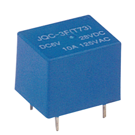
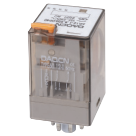
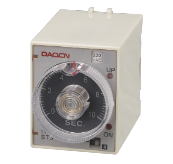
Why DAQCN SSRs Offer Industry-Leading Reliability
At DAQCN, we engineer our Solid State Relays to withstand the harsh electrical environments found in modern industrial facilities. Our high-performance SSR range features
For B2B wholesalers, machine builders, and system integrators, selecting DAQCN means sourcing reliable switching components that minimize field failures and eliminate costly warranty returns.
Conclusion: Optimizing Your Industrial Control Circuits
A Solid State Relay staying ON is a solvable engineering challenge. By systematically diagnosing whether the root cause is input control residual voltage, off-state leakage current, or thermal damage, and by applying solutions like bleeder resistors or transient protection, engineers can maintain stable operations. Standardizing on high-quality components like DAQCN SSRs ensures maximum efficiency, safety, and operational longevity in your industrial automation setups.
Discover DAQUAN’s CE/TUV-certified relays, timers, energy meters & WiFi smart switches for industrial automation. ISO9001 factory in Wenzhou, 30 km to airport, global OEM/ODM.
No. 172, Xinguang Avenue, Xinguang Industrial Zone, Liushi Town
Copyright © 2026 WENZHOU DAQUAN ELECTRIC CO.,LTD All rights reserved. Privacy Policy
 Hot News