
Introduction: The Versatility of the 11-Pin Relay
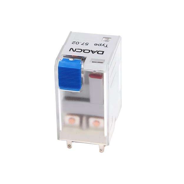
In the field of industrial automation and control panel design, programmable logic controllers (PLCs) are highly prevalent. However, despite the rise of digital controllers, electromechanical relays remain essential for providing physical electrical isolation, signal multiplication, and interlocking logic control. Among these, the 11-pin plugin relay—commonly referred to as the MK series or cylindrical-pin relay—is one of the most versatile and robust components available.
Featuring a three-pole double-throw (3PDT) contact configuration, an 11-pin relay allows a single control signal to simultaneously switch three completely independent electrical circuits. This capability makes it ideal for complex hardwired logic control, such as forward-reverse motor interlocking, safety limit switching, automatic transfer systems, and alarm feedback loops. For B2B engineers, panel builders, and wholesalers, mastering the wiring pinout and logical mapping of an 11-pin relay is crucial to ensuring reliable, error-free system operation. This guide provides a detailed technical breakdown of the 11-pin terminal configuration, standard wiring procedures, and practical logic applications.
Understanding the 11-Pin Terminal Configuration (Pinout Map)
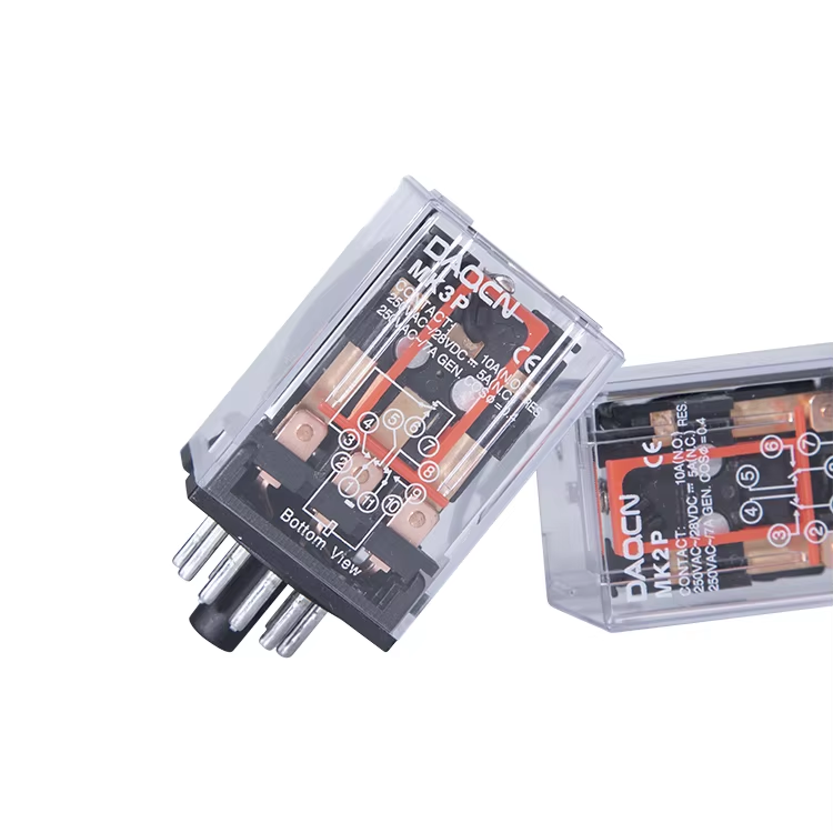
To successfully wire an 11-pin plugin relay, you must understand the standard numbering layout of its cylindrical base. The pins are arranged in a circular pattern, numbered 1 through 11 when viewed from the bottom of the relay (or on the corresponding DIN-rail mounting socket).
According to international electrical standards (IEC), the 11 pins are divided into three distinct functional groups: the operating coil, the common terminals, and the switching contact terminals (Normally Open and Normally Closed).
1. The Operating Coil (Pins 2 and 10)
These two pins supply power to the relay's electromagnetic coil. When the control voltage (which can be AC or DC, depending on the model, such as 24V DC or 220V AC) is applied across pins 2 and 10, the coil energizes, creating a magnetic field that pulls the armature down to switch the contacts.
2. Pole 1 (Pins 1, 3, 4)
This is the first independent single-pole double-throw (SPDT) switching circuit.
3. Pole 2 (Pins 11, 9, 8)
This is the second independent switching circuit.
4. Pole 3 (Pins 6, 7, 5)
This is the third independent switching circuit.
By keeping these three poles completely isolated from each other electrically, you can switch different voltages (for example, using Pole 1 to switch 220V AC for a fan motor, Pole 2 to switch 24V DC for a PLC status input, and Pole 3 to switch 12V DC for an alarm LED) using a single relay coil control signal.
Step-by-Step Professional Wiring Procedure
When building a control panel, always wire to the DIN-rail mounting socket rather than attempting to solder directly to the relay pins. Follow this professional installation procedure:
Step 1: Mount the Socket and Label Your Wires
Step 2: Wire the Control Coil Circuit
Step 3: Wire the Load and Logic Circuits
Depending on your logic requirements, connect your load wires to the appropriate pole terminals. For example, to use Pole 1 as an indicator light control:
When the coil is energized, the red light turns off, and the green light on Terminal 3 turns on.
Step 4: Install the Relay and Secure the Retaining Clip
Practical Logic Application: Forward-Reverse Motor Interlocking
One of the most common B2B applications for an 11-pin relay is to provide physical hardware interlocking between forward and reverse motor contactors. This prevents both contactors from energizing simultaneously, which would cause a catastrophic phase-to-phase short circuit.
Why DAQCN MK Series 11-Pin Relays are the Industry Standard
At DAQCN, we manufacture our MK series 11-pin relays and matching sockets to meet the highest global standards of industrial durability and electrical safety:
Conclusion: Mastering Classic Control Circuits
Wiring an 11-pin plugin relay (MK series) is a fundamental skill for industrial electrical engineers and panel builders. By understanding the circular pin layout, matching common inputs to COM terminals, and leveraging the three independent SPDT poles, you can build complex, highly reliable hardware logic and safety interlocking systems. Choosing premium-grade relays and sockets from DAQCN ensures your control panels operate with maximum stability, precision, and safety, season after season.
Discover DAQUAN’s CE/TUV-certified relays, timers, energy meters & WiFi smart switches for industrial automation. ISO9001 factory in Wenzhou, 30 km to airport, global OEM/ODM.
No. 172, Xinguang Avenue, Xinguang Industrial Zone, Liushi Town
Copyright © 2026 WENZHOU DAQUAN ELECTRIC CO.,LTD All rights reserved. Privacy Policy
 Hot News